5-HMR-12 AMX and ABX Patterns
AMX, ABX and ABC patterns, and various related spin systems are very common in organic molecules. Below some of the structural types which give such patterns.

5-HMR-12.1 AMX Patterns
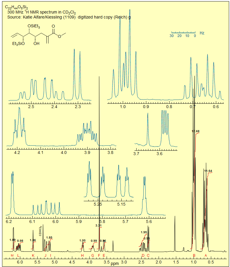
Three nuclei coupled to each other and separated by a large chemical shifts compared to the coupling between them can be analyzed in first order fashion (Sect. 5-HMR-3): the A, M and X signals are each a doublet of doublets, and the couplings can be extracted by inspection. An example:
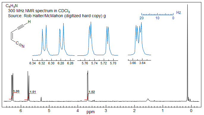
Exercise: How can the assignments for the A and M protons be done in the example below (see Sect. 5.5)?

5-HMR-12.2 ABX Patterns
When two of the protons of an AMX pattern approach each other to form an ABX pattern, the characteristic changes in intensities of a strongly coupled system (leaning) are seen, and, as the value of νAB approaches the size of J more complicated changes arise, so that the pattern can no longer be analyzed correctly by first order methods. A typical ABX spectrum is shown below:

Figure 5-12.1. Sample ABX pattern
For this spectrum νAB is less than twice J, and a first order (AMX-type) interpretation starts to become imprecise, although, in this particular case, it is unlikely to lead to a substantial misinterpretation. On the other hand, for the spectrum below (which is actually an ABMX3, where X = 19F), the second order effects are so large than a first order interpretation may lead to significantly inaccurate couplings, both in magnitude and sign, and a possible mis-assignment of the structure.
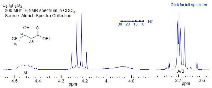
Figure 5-12.2. A borderline ABX pattern (actually an ABM3X pattern, since the X proton is coupled to the three fluorines. First order analysis of this one is problematic.
Even more likely to mislead is the ABX pattern below, for which any form of first order analysis could lead to wildly incorrect structure interpretations, or even a "false negative" during synthesis of a molecule (i.e., your reaction was actually successful, but you conclude that it failed because the NMR spectrum does not appear to fit the expected structure). Fortunately, such degenerate ABX patterns, which used to be an everyday occurrence with 40 and 60 MHz 1H NMR spectra, have become rarer as field strength increased to 200, 300, 500 MHz and beyond.
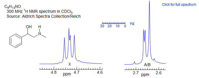
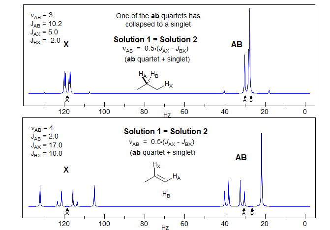
Figure 5-12.3. A deceptive ABX pattern, in which one of the ab sub-quartets has collapsed to a singlet. No first-order analysis possible. For more on this see Section 5-HMR-12.5.
For these reasons, and because ABX systems are subsets of many other patterns with additional spins, we will examine them in some detail. In the progression from first-order NMR patterns to incomprehensible jungles of peaks, they represent the last stopping point where a complete analysis (by hand or hand calculator) is still possible, and where insights into the problems that arise in the analysis of more complex systems can be achieved. Specifically, ABX patterns are the simplest systems which show the phenomenon sometimes referred to as "virtual coupling" (see Sect. 5-HMR-16) and they are the simplest systems in which both the magnitude and the sign of J coupling constants is significant. Furthermore, as illustrated above, there are several pathological forms of ABX patterns which are sufficiently non-intuitive that the unwary spectroscopist can mis-assign coupling constants and even structures.
5-HMR-12.3 Development of an ABX Pattern
Consider the stick diagram below which represents an ABX pattern in which we sequentially turn on first the A-X and then the B-X coupling:
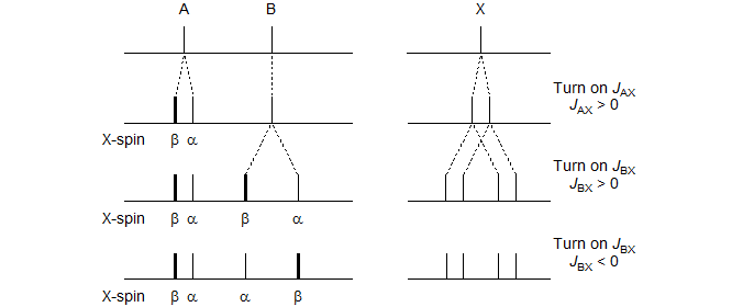
One of the two lines in the A-pattern arises from those molecules with the spin of the X-nucleus aligned against the field (β) and the other from those which have the X-spin aligned with the field (α). Similarly for the B-pattern. Note, however, that the line assignments of the pattern with both JAX and JBX nonzero will be different depending on the relative sign of JAX and JBX, as illustrated in the Figure. Up to this point the line positions are identical.
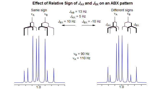
The key to understanding ABX patterns is to realize that the A and B nuclei with spin of X = α and those with spin of X = β are actually on different molecules, and cannot interact with each other. Thus, when we finally turn on JAB, it will be the X = α line of A and the X = α line of B that will couple to form an AB-quartet. Similarly, the two X = β lines will form a second AB-quartet. Since the line intensities and line positions of an AB quartet depend on the "chemical shift" between the nuclei, it is clear that the different relative signs of JAX and JBX will result in different spectra. The ABX pattern is thus the simplest spin system for which the discerning spectroscopist can identify the relative signs of coupling constants by analysis of the pattern. The figure below shows the final AB part of the ABX pattern for the two cases.
5-HMR-12.4 Solving ABX Patterns
Recognizing an ABX Pattern. A typical ABX spectrum consists of an unsymmetrical 8-line pattern integrating to two protons which has 4 doublets with the same separation JAB. Each doublet shows strong "leaning". This is the AB part. The X part is a symmetric 6-line pattern, integrating to one proton, with four lines dominant (often looking like a dd). The 5th and 6th lines (marked with red arrows) are usually small, and not often seen. JAB and νX are directly measurable, the other parameters (JAX, JBX, νA, νB) must be calculated. For additional examples of solved ABX and related patterns see: 1, 2, 3, 4, 5, 6, 7, 8.

The AB part consists of two superimposed ab quartets (8 lines) which have normal intensities and line separations, both of which have identical JAB values, but can have very different νab values. We will use "a" and "b" for the AB-subquartets of the AB part of an ABX pattern. Occasionally one of the ab quartets has νab = 0, and all four lines are collapse to a singlet (or more precisely, the inner two lines are superimposed, and the outer two have zero intensity). Such systems appear as a five line pattern, with one ab quartet and a singlet (see Fig. 5-12.3 for an example). There are also several other deceptive forms with one or more lines superimposed.
The X part usually consists of an apparent doublet of doublets, although apparent triplets are not uncommon. There are two other lines which are often too weak to be detected (total of 6 lines). They become large for close-coupled systems when JAB > νAB.
First Order "AMX" Type Solution. Many ABX patterns are sufficiently close to AMX (i.e., νAB>>JAB) that a first-order solution has an excellent chance of being correct, and of giving accurate values for JAX and JBX. We identify the distorted doublet of doublets (JAB, JAX) which make up the A portion, as well as the dd (JAB, JBX) for B, and begin the analysis by first removing the JAX and JBX couplings, respectively. This leaves us with an AB pattern, which we can solve in the usual way. Since this is a first-order analysis there is no information about the relative signs of JAX and JBX.
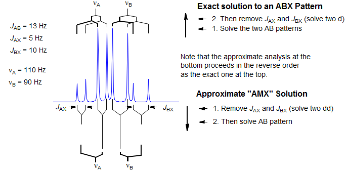
For ABX patterns which are of the "Solution 1" type (see below) this analysis will lead to J and δ values that are quite close to correct. The errors become larger when JAX and JBX are very different in size (especially if they are different in sign) and, of course, when νAB is small compared to JAB. However, such an analysis, carelessly applied, can be completely wrong if the system is of the "Solution 2" type.
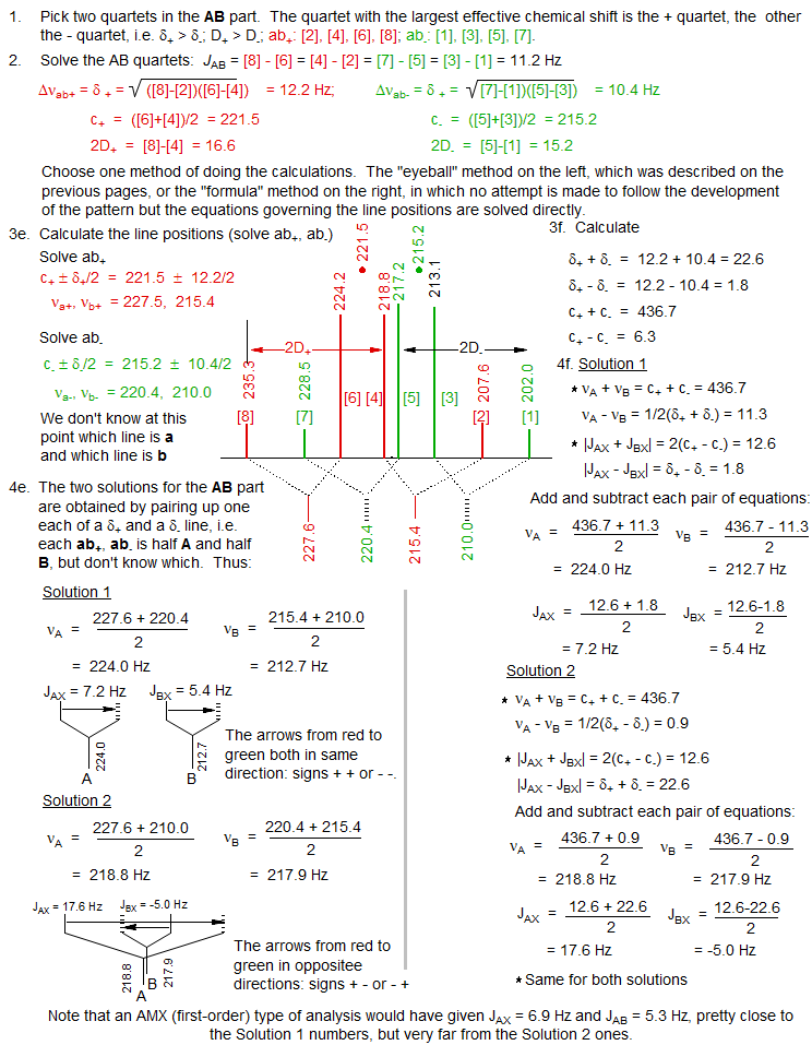
Correct Analysis of ABX Patterns. In order to correctly analyze an ABX pattern of arbitrary complexity we have to reverse the order of extraction of coupling constants compared to the AMX solution above. We have to first solve for JAB, and then for JAX and JBX. Proceed in the following order:
1. Identify the two ab quartets. These can usually be recognized by the characteristic line separations and "leaning." We will use the notation ab+ and ab- for the two quartets (+ identifies the one with the larger νab). Number the lines of one ab quartet 2,4,6,8 and the other 1,3,5,7 (NOTE: these line numbers will not typically be in sequence in the spectrum). Check to make sure that Jab+ = Jab-, and that the ab quartet with the taller middle lines has the shorter outer lines. Note that ABX patterns are not affected by the sign of JAB.
If the ABX pattern verges on AMX (νAB/JAB >> 2), then line intensity patterns will not allow unambiguous choice of ab subquartets. Such systems can normally be analyzed as an AMX pattern, but with the limitation that the relative sign of JAX and JBX is indeterminate. If you complete the full ABX treatment with the wrong assignment of quartets, the signs of JAX and JBX will be wrong, and there will be small errors in their magnitude. This could ultimately lead to a wrong Solution 1/2 assignment (see below) if you use the signs of couplings to make the distinction.
Another situation in which the choice of ab subquartets can be difficult is in systems verging on ABC, where all of the line intensities are distorted. This is where computer simulations might become necessary.
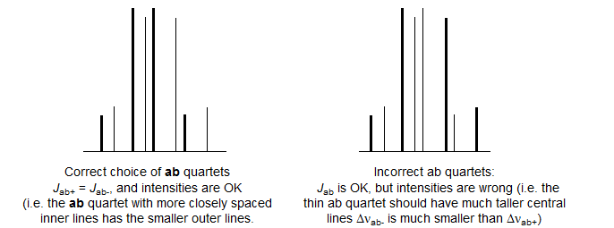
2. Solve the two ab quartets. Treat the ab subquartets as normal AB patterns, and obtain the four "chemical shifts," νa+, νb+ and νa-, νb-.
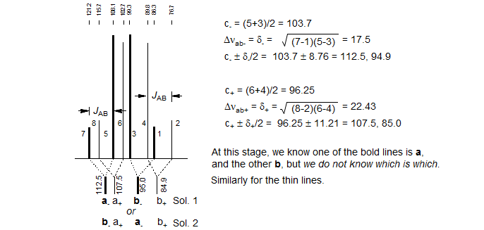
3. Identify the correct solution. At this point in the analysis we encounter an ambiguity. We know that each of the ab quartets consists of two a and two b lines, but we do not know which half is a and which is b. There are thus two solutions to all ABX patterns which have two ab quartets. (The only exceptions are those ABX patterns in which one of the ab quartets has collapsed to a singlet. For these there is only one solution.) The two solutions are obtained by pairing up one each of a δ+ and a δ- line (i.e. in the stick spectra shown, pair up one bold and one light line - solution 1 corresponds to pairing up the nearest neighbors, solution 2 to the remote ones, where we have swapped the a-/b- assignments of the bold lines). The analysis is completed as below:
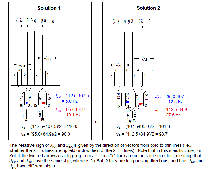
As part of the solution we obtain the relative signs of JAX and JBX. In the example above, this means that for Solution 1 the couplings are either both positive or both negative, and for Solution 2 one is positive and one negative. Note that there are also ABX patterns where the signs of JAX and JBX are the same in both solutions, and where they are different in both solutions.
The relative signs of JAX and JBX are determined by the way in which the ab quartets overlap. For the statements below, "lines" refers to the νa and νb line positions obtained by solving the ab- and ab+ quartets. Solution 1 is defined as the one with the larger difference between νA and νB. Thus Solution 1 always has the least distorted X-part. The vectors are drawn from a- to a+ and from b- to b+ (bold to thin) in each case.
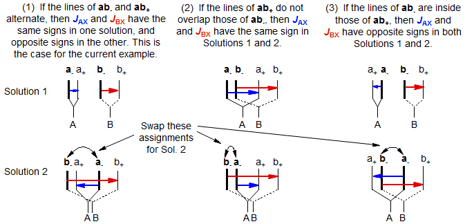
Distinguishing Between Solutions 1 and 2. Which solution is the correct one? Several criteria can be used to make the assignment:
1. Magnitude of the couplings. Sometimes one of the solutions gives unreasonable couplings. In the example above, if we are dealing with proton-proton couplings, Solution 2 looks dubious because one of the couplings, JBX at 27.6 Hz, is larger than usually observed for JHH. A coupling this large is not impossible for a proton spectrum, but rather unlikely.
2. Signs of coupling constants. Sometimes the sign of the coupling constants is definitive. If the structure fragment is known, the signs can sometimes be predicted, and may rule out one solution. For example, all vicinal couplings (3JHCCH) are positive, geminal couplings (2JHCH) at sp3 carbons are usually negative. A common structure fragment which gives ABX patterns is CHX-CHAHB. Here both JAX and JBX must have the same sign. On the other hand, if the pattern is CHA-CHBHX (a much less common situation) then the signs must be different. Note, however, that if you misidentified the ab subquartets, then the signs of the coupling constants you calculated may be wrong.
3. Analysis of the X-Part. It is important to note that all lines have identical positions in both Solutions 1 and 2. The intensities of the AB part are also identical for both solutions. However, the intensities of the lines in the X-part are always different, and this is the most reliable and general way to identify the correct solution.
For the vast majority of ABX patterns encountered in organic molecules, Solution 1 is correct. Solution 2 spectra are found when A and B are close in chemical shift and the size of JAX and JBX are very different, and especially when they have different signs.
Checking your solution arithmetic. There are a couple of checks you can run to make sure that there has not been a calculation error:
1. The difference in the centers of the two ab quartets should be half the average of JAX and JBX:
| c+ - c- | = 1/2[JAX + JBX]
2. The average of the two centers should be equal to the average of the two chemical shifts:
1/2 | c+ + c- | = 1/2 | νA + νB |
Analysis of the X-Part of ABX Patterns. The X part of an ABX pattern is maximally a centrosymmetric 6-line pattern. However, in many cases it closely resembles a doublet of doublets, and it is often treated as such. However, the couplings obtained are only approximate. The errors become larger when JAX and JBX differ greatly in size, and especially if they have different signs. The sum of JAX + JBX will be correct, but the individual values will be incorrect, with the errors increasing as νAB becomes smaller. The values of JAX and JBX will be completely wrong if we are dealing with a Solution 2 pattern.
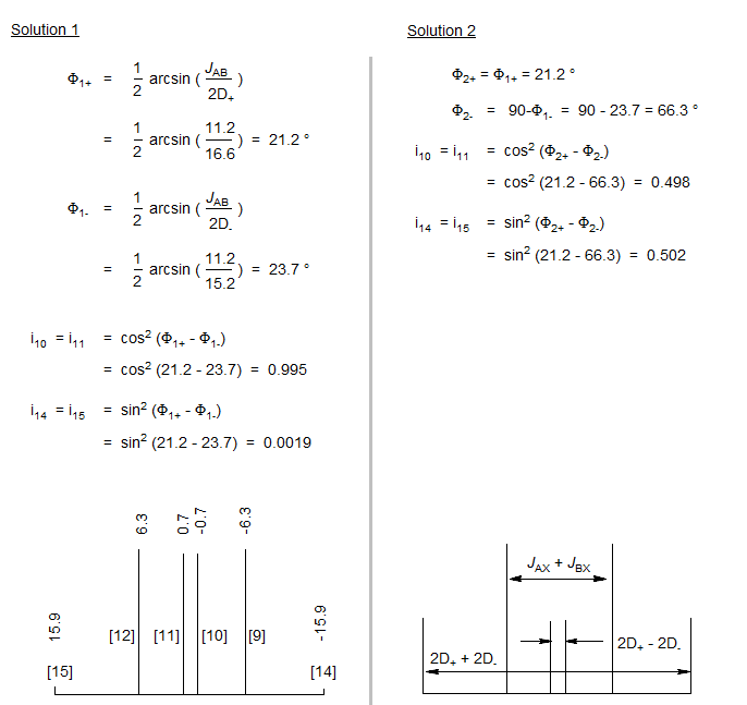
The X-part consists of 6 lines, of which only four are usually visible. The two additional lines are often weak, but can be seen in Solution 2 patterns for which νA and νB are close together, and the X-part is consequently significantly distorted. The lines are numbered as follows: the two most intense are 9 and 12, they are separated by JAX + JBX. The inner pair of the remaining lines are 10 and 11, their separation is 2D+ - 2D-. The outer lines (often invisible) are 14 and 15, separated by 2D+ + 2D-. Line 13 has intensity of zero. These line assignments are not always straightforward: sometimes lines 10 and 11 are on top of each other, resulting in a triplet-like pattern, sometimes 10 and 11 are very close to 9 and 12, leaving just a doublet.
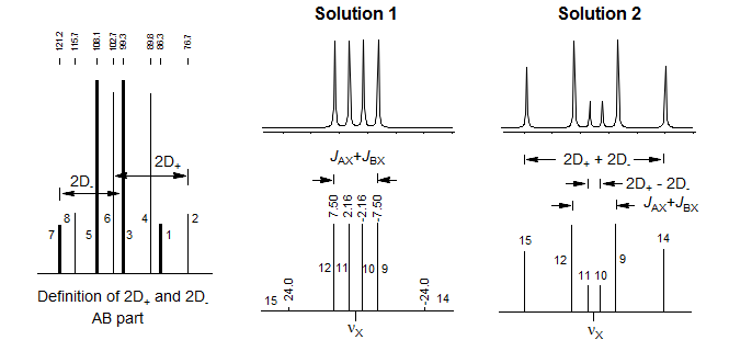
To carry out an intensity calculation we define lines 9 and 12 to have intensity 1 (i9 = i12 = 1.0), and proceed as outlined below:
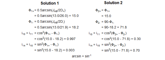
Solving an ABX pattern - Summary
Below is another example of an ABX pattern solution. The "eyeball method" is the one described here, the "formula method" is the one commonly presented in NMR books. We recommend the "eyeball" method" because it follows the actual coupling tree in a systematic manner, whereas the "formula method" extracts the information in a mathematically correct but non-intuitive fashion. Both will give identical answers.
5. Analyzing the X Part
Solution 1 and Solution 2 are defined such that Solution 1 has the larger νA - νB value (i.e. the larger chemical shift difference between the A and B nuclei). Hence Solution 1 always corresponds to the one with the least distorted X part. To properly identify the correct solution in ambiguous cases it is necessary to do an intensity calculation. The six X lines are numbered as follows: the two most intense are 9 and 12, they are separated by JAX + JBX. The inner pair of lines are 10 and 11, their separation is 2D+ - 2D-. The outer pair of lines (often invisible) are 14 and 15, separated by 2D+ + 2D-. Line 13 has intensity 0.
Define the intensity of lines 9 and 12 = 1.0, and calculate the relative intensity of lines 10 and 14. For this example Solution 1 has a fairly normal appearance close to a dd, whereas Solution 2 has all 6 lines clearly visible.
5-HMR-12.5 5-Line ABX Patterns
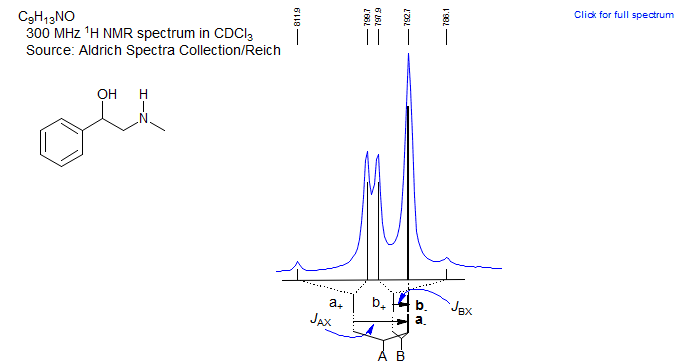
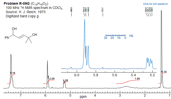
The most deceptive type of ABX patterns are those in which one of the ab sub-quartets has collapsed to a singlet (Δνab- = 0). For these only 5 lines are seen: a singlet for one ab subquartet and the usual four lines for the other. See the material on the next pages as well Figure 5-12.3 for examples. Such systems represent the crossing point between Solution 1 and Solution 2 situations, and for these there is only one solution (Solution 1 = Solution 2). The apparent dd X-part is always deceptive. Such ABX patterns are solved exactly the same way as normal ABX patterns, except that for one of the ab quartets the two chemical shifts νa- and νb- are identical. Only one ab quartet has to be solved. This is illustrated below. Other examples: 1, 2, 3, 4, 5, 6, 7, 8, 9, 10, 11.
Another example below:
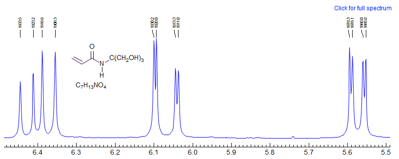
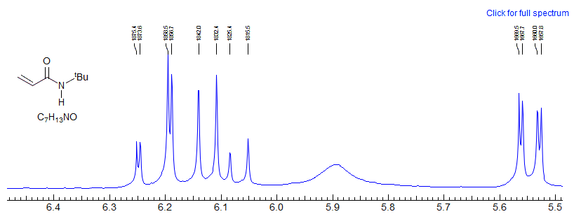
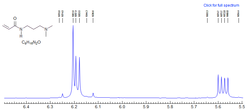
Example of a vinyl spin system going from AMX to ABX as the chemical shift between two protons changes with N-substitution.
Exercise: Determine coupling constants for the "AMX" systems 1 and 2, and for the bottom spectrum 3 by a proper ABX analysis,
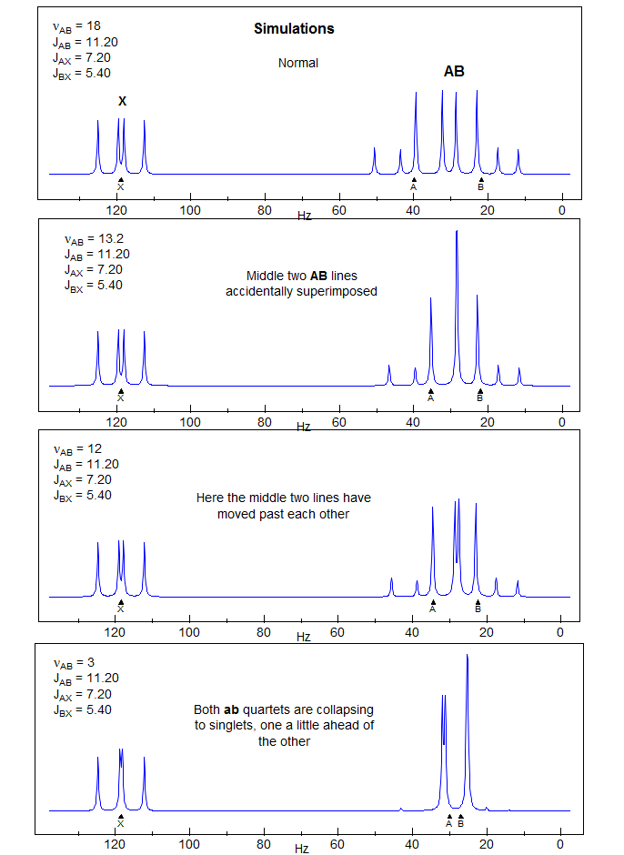
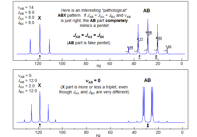
A look under the hood of ABX patterns. Actually, it is not the chemical shift per se between A and B that determines the extent to which ABX patterns are completely misleading, but rather the coincidence of lines that share transitions. This can be seen by an analysis of a situation where JAX is much larger than JBX, as would be the case for a structure fragment H-13C-C-H. Here the spectrum is most deceptive when νAB = 0.5 JAX.
When νA and νB are superimposed, the X part shows only a minor perturbation
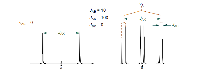
When is νB superimposed on one of the "13C satellites" of A (when νAB = 0.5 JAX), the X part shows full-blown false multiplet structure (easily mistaken for a doublet of triplets ??).
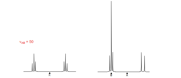
This reinforces the point made several times in these notes: when looking at an X-nucleus (i.e.one far away from others that it is coupled to) it is tempting to take the multiplet structure at face value. However, the X-part will contain misleading information if the AB parts are strongly coupled - that is, if νAB is comparable to or lss that JAX or JBX. More specifically, the X part will be most distorted when νAB = 0.5(JAX - JBX). This is, in fact, the crossing point from Solution 1 to Solution 2.
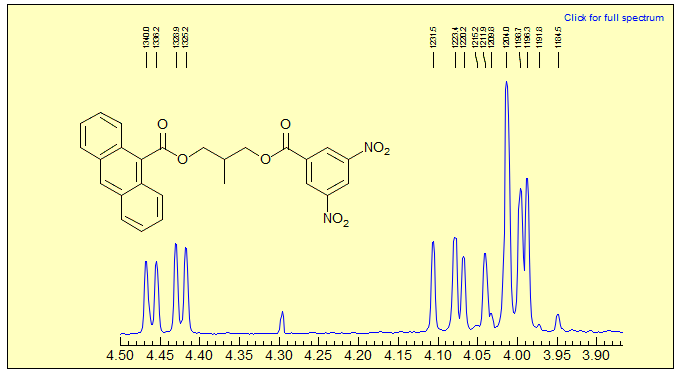
Exercise: Analyze the peaks below, which correspond to the AB and XY parts of an ABMXY pattern. Source: Heaton JACS 1998, 120. 9636. DOI
Deceptive ABMX patterns. Of course, the same phenomena that result in the occasional very deceptive 5-line ABX pattern, can also occur with larger spin systems, i.e. ABMX patterns. An example is shown below:
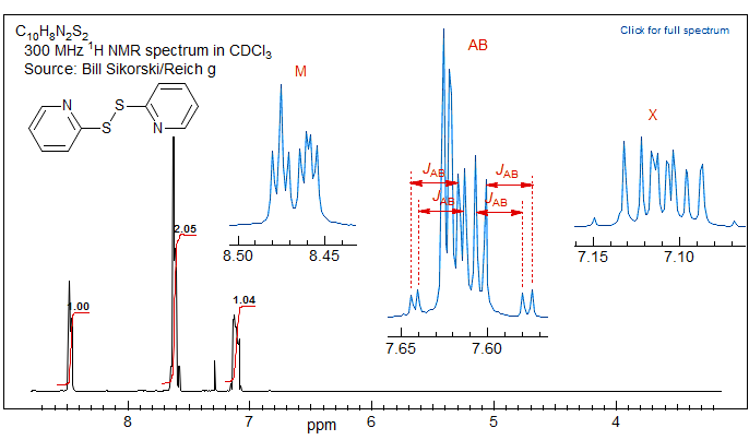
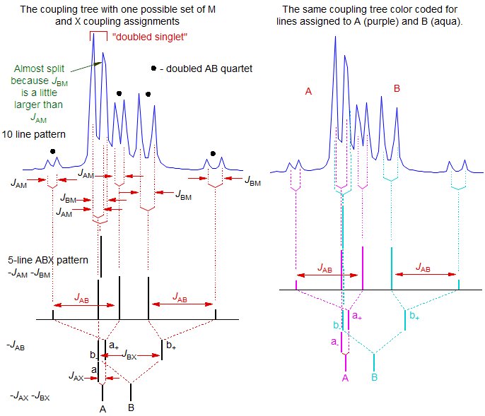
Here the AB part is a 10-line pattern (although an eleventh line is almost resolved), corresponding to the 5-line ABX pattern discussed above (that is, a singlet and an AB quartet), where each peak has been doubled by coupling to the M proton. The two protons are ortho to each other, as can be seen from the JAB, which, as for ABX patterns, can be read directly from the multiplet as shown.
A qualitative analysis is shown below. Note that the "singlet" in the 5-line ABX pattern is actually two (nearly) superimposed lines, one an A line, and one a B line. Thus in this 10-line pattern each half will be split differently by M, one by JAM and the other by JBM. These couplings are very similar, but account for the "attempted" splitting of the right line of the doubled singlet (marked).
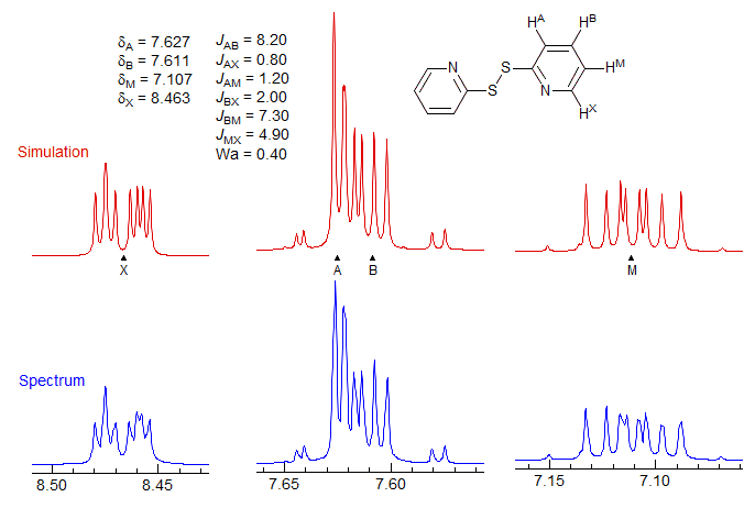
The above analysis assigned the small couplings to JAM and JBM as indicated, but JBM could just as easily have been assigned to JBX - the analysis is the same - only examination of the M and X multiplets will allow a distinction between the two assignment to be made. In fact, the assignments above are the correct ones, as shown by a WINDNMR computer simulation of the spectrum, which also allows assignment of the protons as shown.
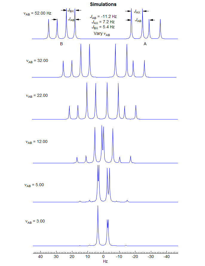
5-HMR-12.6 A Simple ABX Pattern as νAB is Changed
5-HMR-12.7 Effect of Relative Sign of JAX and JBX on ABX pattern
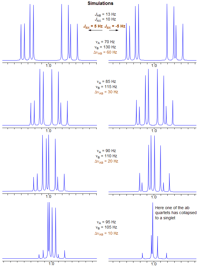
5-HMR-12.8 ABX with Accidental Coincidences
5-HMR-12.9 ABX of the Vinyl Type - terminal protons close δ
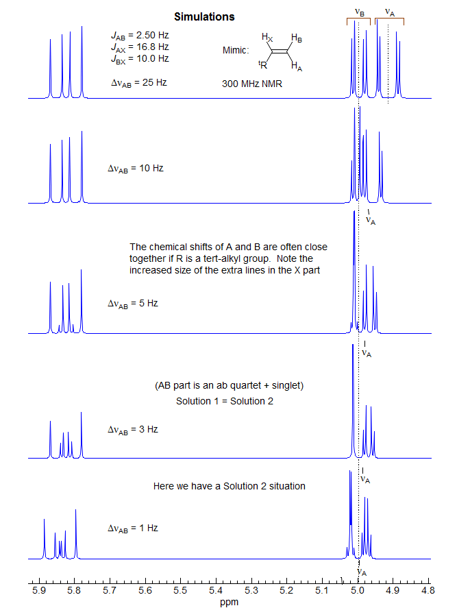
For an example see: 1.
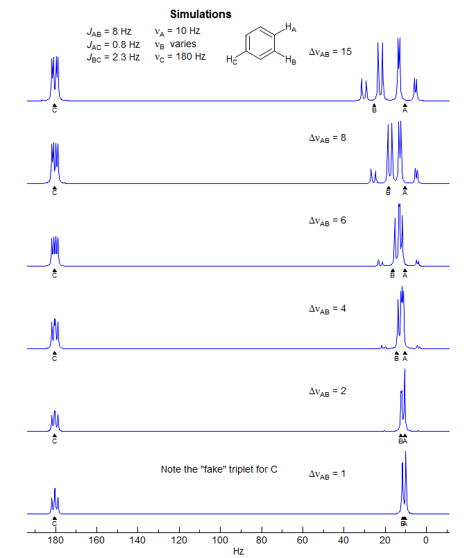
5-HMR-12.10 ABX Going to ABC
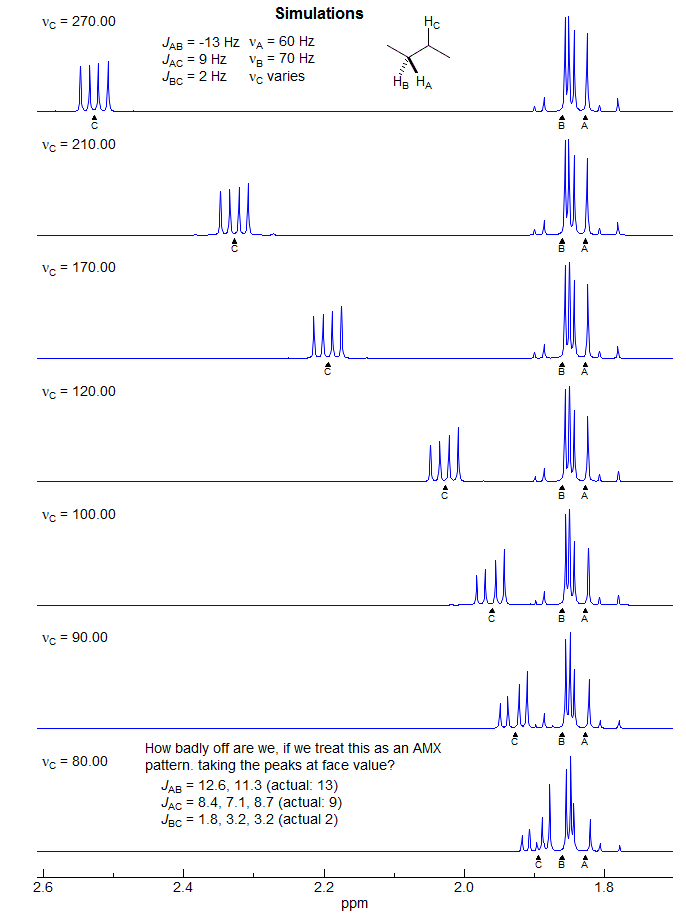
ABX Going to A2X
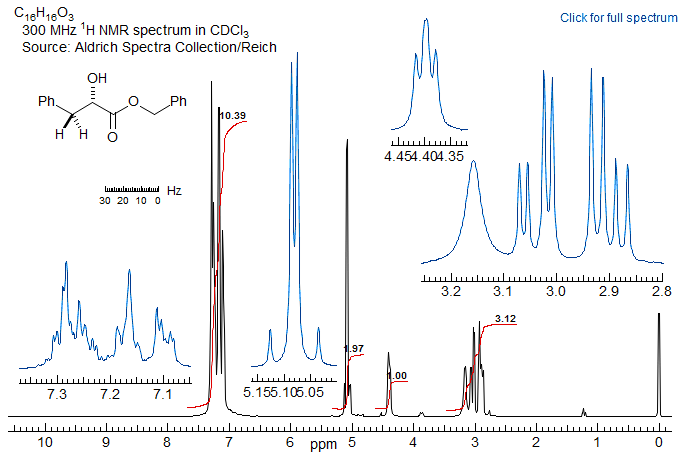
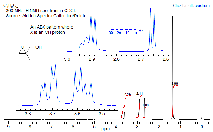
5-HMR-12.11 Sample ABX Spectra

5-HMR-12.12 ABMXY Spectra
Part structures like R1-CH2-CH-CH2-R3 are actually two ABX patterns which share a common X. If νAB and νXY are large enough they can be close to first order. Examples: 1, 2, 3, 4, 5, 6, 7, 8, 9, 10, 11, 12, 13.
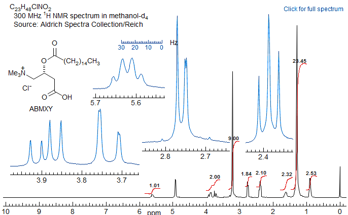
If R1 and R3 are the same, then the pattern is technically AA'BB'X but shows no unusual complexity because there is no significant coupling between the A and A' protons, nor between the B and B' protons. Such systems are better defined as (AB)2X to indicate that magnetic inequivalence is not a significant factor. Examples: 1, 2, 3, 4, 5.
5-HMR-12.13 ABXmYnZo Patterns
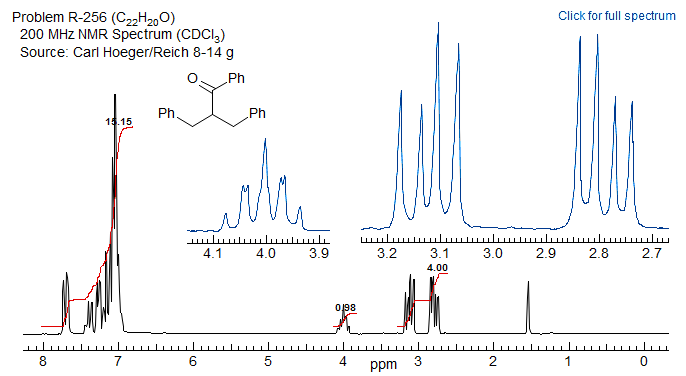
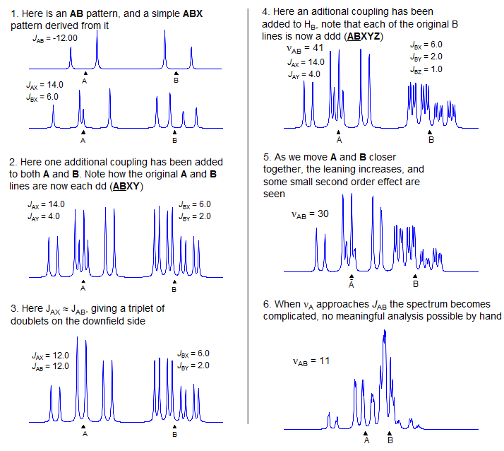
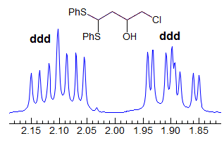
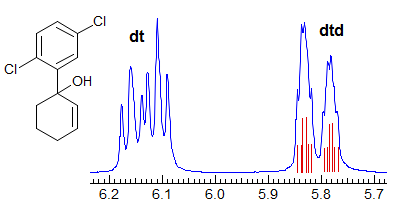
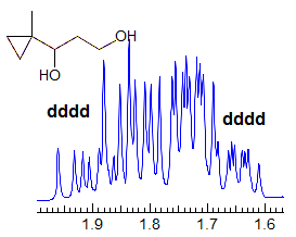
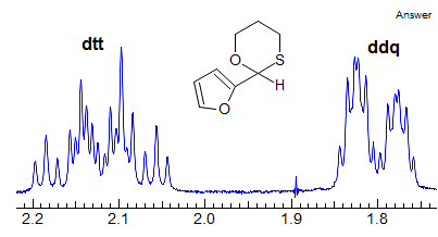
In real molecules AB patterns that are coupled to more than just one X proton appear frequently. There may be several X protons (ABX2, ABX3) or there may be two or more different protons coupled to the AB part (ABXY, ABXYZ). Some part structures illustrate these common types:

Most such spectra can be at least approximately analyzed in a straightforward fashion using an AMX-type approach, by treating the two A lines of the parent AB quartet as each being split into a dd, ddd, dddd, dt, etc by the X, Y and Z protons. Similarly for the two lines of the B part. Fortunately there is usually no Solution 1/Solution 2 ambiguity, since the A lines and B lines can be distinguished because each shares common couplings. Examples: 1, 2, 3, 4, 5, 6, 7, 8, 9, 10, 11, 12, 13, 14, 15.
Examples of ABXmYnZo Patterns
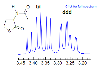
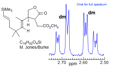
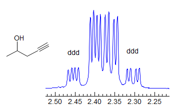
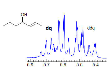
More Examples of ABXmYnZo Patterns
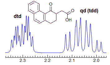
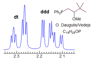

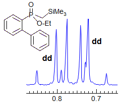
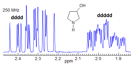
More Examples of ABXmYnZo Patterns
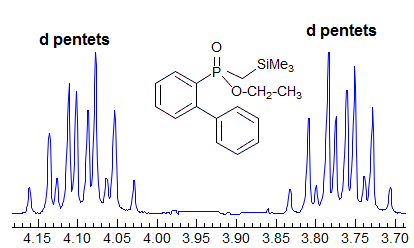
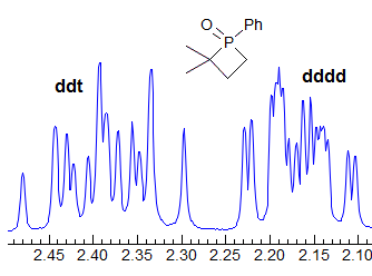
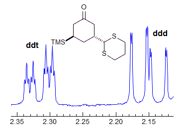
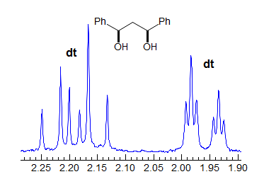
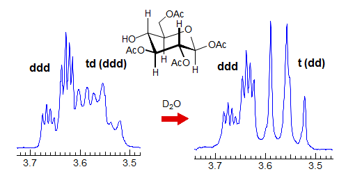
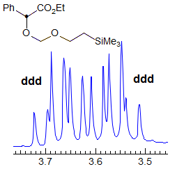
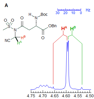
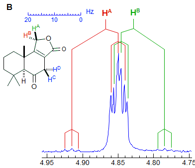
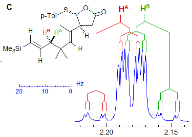
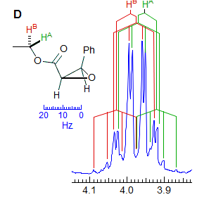
When the chemical shift between the A and B protons in ABXYZ... patterns becomes small, the resulting multiplets can be very deceptive. Basically a chemical shift-based separation can mimic a coupling constant. A simple example would be mistaking a closely-spaced AB quartet for a doublet (Spectrum A). At first glance the multiplet in Spectrum B looks like a triplet of doublets J = 2.4, 1.1 Hz. However this makes no sense, given the structure. A more careful look shows that this is really an ABq, (JAB = 17 Hz) each line of which is split into triplets (J = 2.4 Hz). The triplet splitting is a five-bond homoallylic coupling to HC, HD. Note that the J-values obtained from the AMXYZ-type coupling trees will be only approximately correct. For another example see: 1.
Another example is shown in Spectrum C, an ABq of dd, which could be mistaken for a ddd, especially if the spectrum is noisy enough to partially obscure the outer lines (or the NMR operator does not even plot them out in an expansion!). The apparent qd in Spectrum D (which by no stretch of imagination can be assigned to the structure) is actually the AB part of an ABX3 system (an ABq of q), the small outer quartets (marked) are barely visible. See the section on ABX3 patterns (5-HMR-13) for other examples.
Next Section: ABX3 patterns · Previous Section: AB2Pattern · Home
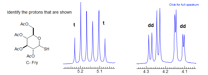
Exercise: Analyze multiplets and assign the protons in the NMR spectrum below.
